We specialize in hard to find items

All Categories


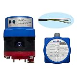
"AD24-2T" DC 24V Motorized Actuators(Excluding Ball Valve) – by VALCON (DC 24V (Waterproof), 2-wire(20 N.M))
Share Tweet
*Price and Stocks may change without prior notice
*Packaging of actual item may differ from photo shown
- Electrical items MAY be 110 volts.
- 7 Day Return Policy
- All products are genuine and original
- Cash On Delivery/Cash Upon Pickup Available


"AD24-2T" DC 24V Motorized Actuators Features
-
Application the ball valve types
-
CE, RoHS Certifications
-
Long life cycle & Manual Function
-
Watchdog the ON/OFF
-
Temperature and timer setting(all parts organized)
About "AD24-2T" DC 24V Motorized Actuators
Actuator Model: AD24-2T Control : DC forward / reverse control Power : DC24V (1A) Consumption Power : Approx. 2.4W (in no-load operation) Standby Power : Approx. 0.1W (in completed) Max. Output torque : 200Kgf‧cm Weight : Approx. 845g Rotation Direction : Closes clock-wise / Opens Counter-clock-wise / (TOP VIEW) Operating time : Approx. 8sec (90° operating basis) Mechanical Life Span : Approx. 100,000 Cycles Operation Environment : indoor IP Rating : IP 67 Certification : CE, RoHS Operation Temperature (Humidity) : room temperature (35 ~ 85% RH) ※ Do not connect black wires to the red wire Installation Specifications 1. Compose system that can control by Close-operating Red(DC 24V + conductor), black (DC 0V - conductor) / Open-operating Red (DC 0V - conductor), black (DC 24V - conductor). It is a forward/reverse control method that operates by changing the direction of current 2. Install actuator vertically to valve that is established in piping line 3. Attach the power supply unit with a switch or disconnecting device for emergency power off 4. Connect an overcurrent cut-off device to the power supply for circuit protection CAU TION 1. Be sure to read the product manual enclosed in the product before installation 2. Refer to the wiring diagram of the electric actuator for wiring carefully