All Categories
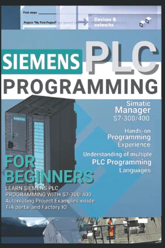


SIEMENS PLC PROGRAMMING FOR BEGINNERS: LEARN SIEMENS PLC PROGRAMMING WITH S7-300/400 Automating Project Examples inside TIA portal and Factory IO
Share Tweet
Get it between 2024-12-04 to 2024-12-11. Additional 3 business days for provincial shipping.
*Price and Stocks may change without prior notice
*Packaging of actual item may differ from photo shown
- Electrical items MAY be 110 volts.
- 7 Day Return Policy
- All products are genuine and original
- Cash On Delivery/Cash Upon Pickup Available






About SIEMENS PLC PROGRAMMING FOR BEGINNERS: LEARN
Brief Description ✓Recognize S7 hardware and be able to replace modules when they fail. ✓To do specific operations, you must use the Step 7 software. ✓Understand the basic S7 instruction set and perform minimal software changes. ✓When necessary, be able to backup and restore a PLC program. ✓When an issue arises, be able to run basic system diagnostics. ✓Learn how to communicate from a PLC to Factory IO. ✓Make changes to the PLCSIM and Factory IO. To find a system, you must first understand how it operates. Then you'll need to understand the details. HOW DO I GO ABOUT DOING THE FOLLOWING? (Some are straightforward, while others aren't) How can I ensure the electricity is turned on and the PLC is set to the correct mode? (RUN or Program). Look for any signs of a problem (is SF LED ON). Make a connection to the PLC (accessible nodes). Check the PG/PC interface if you have a communication problem. Make a backup of your existing project by creating a new one (just in case I mess up). Open a PLC project and go online. Buffer for Interrogate Diagnostics. Determine whether the problem is caused by hardware or software. If required, switch modules (with spares and without spares). Determine whether the issue is with the PLC or the communications system (PLCSIM). ✓Check all settings, such as Node Address, against a template. ✓Examine the hardware configuration. ✓Download the application and clear your memory. ✓Compare the software to the most recent version (Compare function). ✓Program to keep an eye on. ✓Specific operands and instructions are sought. ✓Changing the timer and counter values in real-time. ✓Offline and online minor modifications. ✓To determine parameter status, check or construct a VAT table. ✓If necessary, force a parameter. ✓To assist with software diagnostics, call up reference data. ✓Project Archive and Retrieval. ♥Documentation is displayed (Symbols, Comments). ♥Change software addresses and reassign an I/O address (Rewire Function). ♥Configuration of Analog Inputs at a Basic Level. ♥Printing cross-references, program listings, and other information. ♥Using PLCSIM to communicate from an 3D Simulator to a PLC. ♥Add pushbuttons, a data display, and alarms to an existing 3D Simulator. There was also some background information provided. The following is to be understood: ✓Bits, bytes, words, and double words are examples of number formats. ✓Integer, binary, HEX, octal, floating-point ✓Data types and parameter types, such as Bool, are examples of data types and parameter types. ✓Types that change (local and global) ✓How to keep track of various blocks ✓Programs ladder ✓Contacts, Set, Reset, and Other Basic Instructions ✓Counters and Timers ✓Scalling ✓How to make minor alterations ✓Values in a VAT table can be changed. ✓Going backwards through a program to see where the power flow stops ✓Reset method in general ✓Tips for spotting flaws Documentation for the Course ◆Reference Guide for Simatic Manager S7 ◆SIMATIC STEP 7 (TIA Portal) ® Equipment for the Course ★PLC S7 300 or 400. ★PLCSIM. ★Laptop or PC? ★Simulator Factory IO.


