All Categories


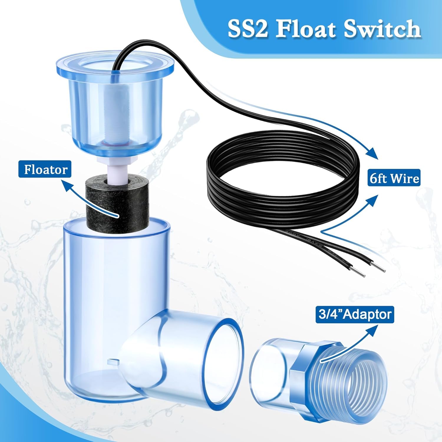
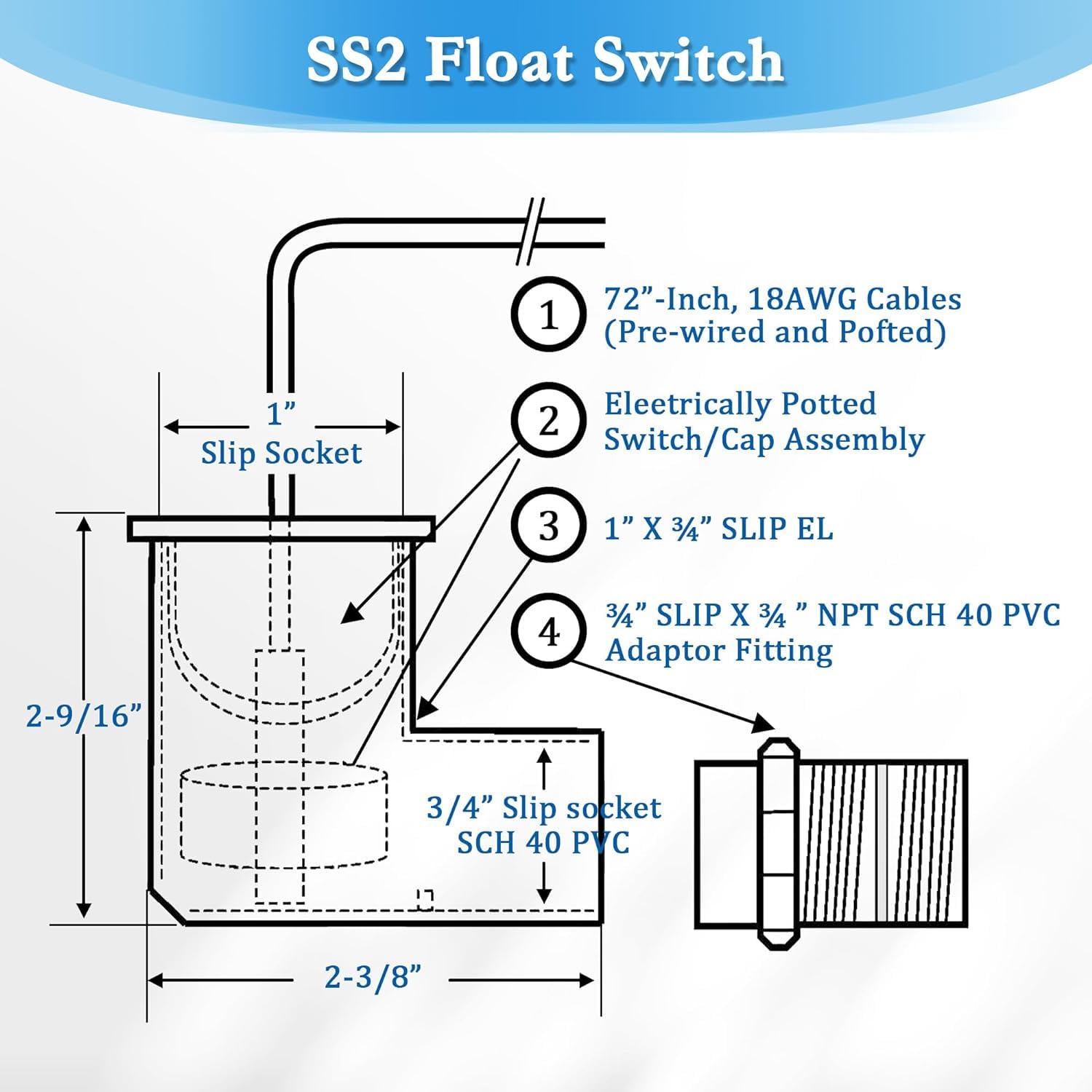

Feekoon SS2 Float Switch L Shape, AC Float Switch with 3/4 Inch Adaptor and 6Ft Wire, Water Float Switch for HVAC System with Condensate Overflow Detection (2 Pack)
Share Tweet
Get it between 2024-12-17 to 2024-12-24. Additional 3 business days for provincial shipping.
*Price and Stocks may change without prior notice
*Packaging of actual item may differ from photo shown
- Electrical items MAY be 110 volts.
- 7 Day Return Policy
- All products are genuine and original
- Cash On Delivery/Cash Upon Pickup Available


Feekoon SS2 Float Switch L Shape, AC Float Switch Features
-
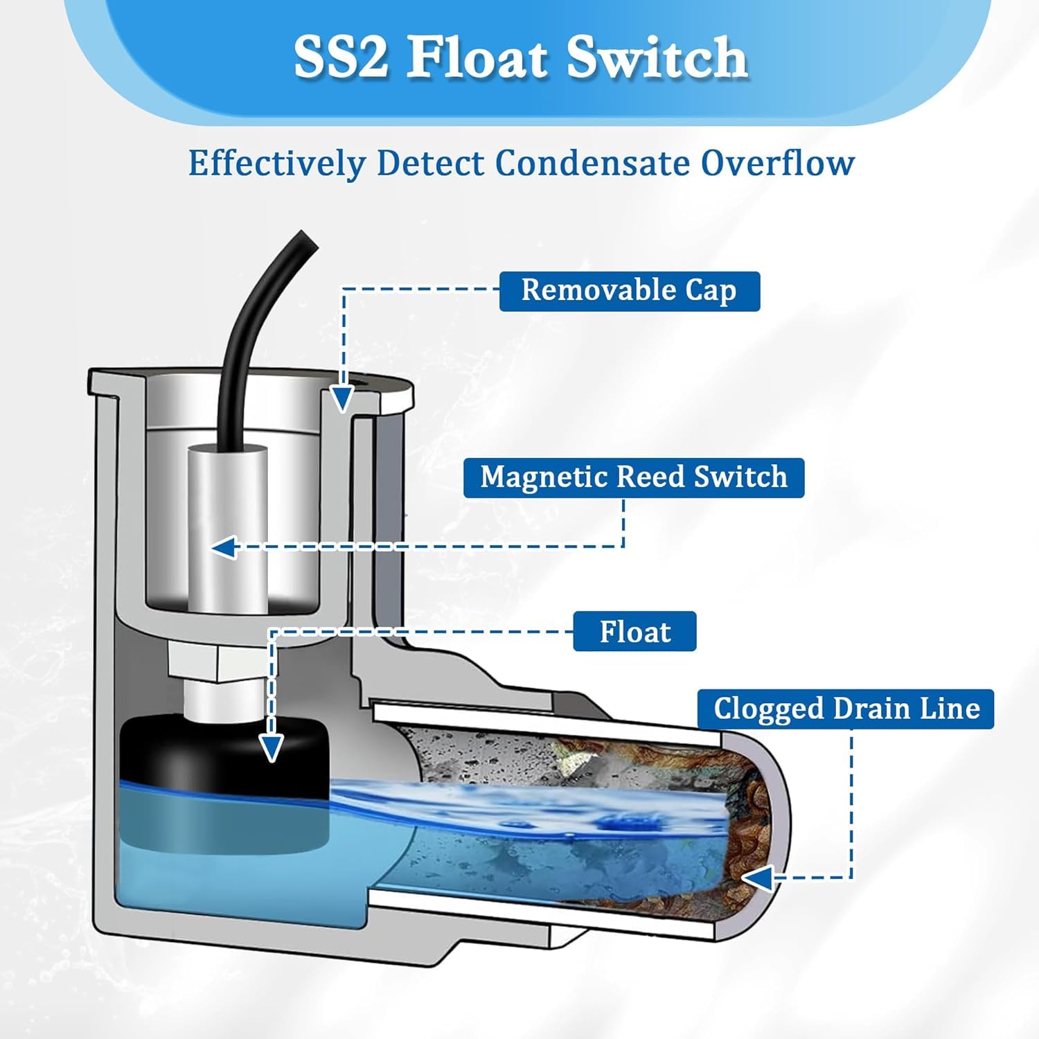
HVAC Float Switch Function: SS2 water level switch is applied in HVAC systems to detect condensation water overflow; It detects blockage of air conditioning condensate water drain pipe and shuts down the system to prevent overflowing water from damaging floors, walls, and ceilings
-
Working Principle: the float switch HVAC can be connected to a VCC or thermostat line; It is an NC type (normally closed) switch: when no water overflows, the float stays at the bottom of the switch, the switch closes the loop and outputs an ON signal; When the water overflows, the buoyancy of the float rises, the trigger switch turns on, and the output OFF signal turns off
-
Specifications: switch type NC ( normally closed) , material PVC, operating temperature -20 ~ + 80℃, wire length 5.8ft, switching voltage Max; 200VDC; Switching current Max; 1 A contact rating Maximum 10W
-
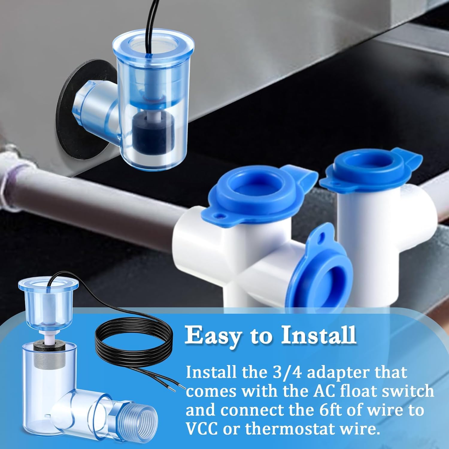
Easy to Install: this float switch HVAC is easy to install, all you need to do is install the 3/ 4 adapter that comes with the AC float switch on the auxiliary drain outlet of the main panel and connect the 5.8ft of wire to VCC or thermostat wire
-
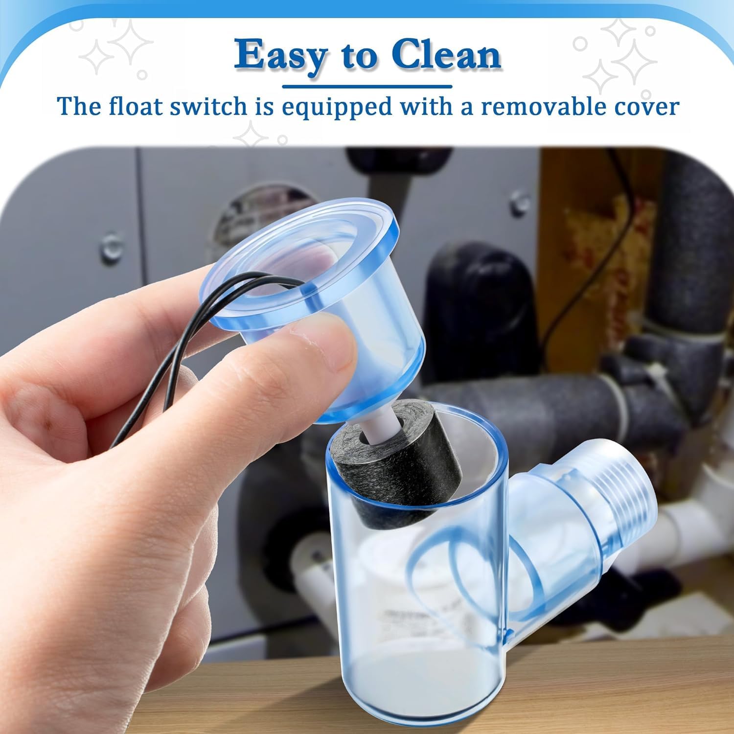
Easy to Clean: the transparent material allows you to see what's going on inside; The float switch is equipped with a removable cover; When you use it for some time, you can remove it for cleaning to ensure hygiene and normal function
About Feekoon SS2 Float Switch L Shape, AC Float Switch
Are you still worried about soaking your furniture due to condensation leaks when using your HVAC? Then you absolutely need a float switch! Here are the specific installation steps for you: INLINE INSTALLATION FOR (WALL) UNITS WITH VERTICAL DRAIN OUTLETS It is recommended that this device be installed on the primary drain line between the pan outlet and P trap on wall units with vertical drain outlets. This will prevent the switch from shutting off the fan coil or activating the alarm circuit in the event condensate drips directly from the coil into the auxiliary pan outlet when the coil becomes dirty. 1. Disconnect power to unit at main panel and glue 5'' stub down from the primary pan outlet. 2. Glue 3/4'' Tee to bottom of stub with Tee stem horizontal and plumb. 3. Glue 3/4'' stub into horizontal outlet of Tee, insuring it is also plumb. 4. Ensure switch/plug assembly is inserted into 1'' inlet of PVC elbow so that float stem is at inside (bottom) of switch elbow. Float stem can be adjusted by threading it out of the plug assembly. DO NOT GLUE. 5. Glue a drain line with P trap onto the remaining outlet of Tee. 6. Connect the wires to VCC or the thermostat wires. 7. Test switch by lifting float with unit running. Unit should stop running if correctly connected. 8. Test all fittings and connections for plumbing leaks. INSTALLATION FOR HORIZONTAL CEILING (PANCAKE) UNITS NOTE: Primary drain (inline) is also recommended on horizontal ceiling (pancake) units as some flooding may occur if installed on auxiliary outlets, due to the closeness of the outlets to the top of the pan. 1. Glue 3/4'' stub to primary pan outlet. 2. Glue 3/4'' Tee onto stub with Tee stem positioned horizontally away from the unit and plumb. 3. Follow steps 3-9 under INLINE INSTALLATION FOR WALL UNITS, above.


 (2)
(2)


